• 1
  • 2
  • 3
  • 4

Recruitment notice of Topdiode

Recruitment notice of Topdiode
Topdiode Manufacturing Company is a leading manufacturer and supplier of a wide range discrete components, such as General Purpose Rectifier, Switching Diode, Zener Diode, TVS Diode, Schottky Diode, Bi-directional Trigger Diode, Fast Recovery Diode, Bridge Rectifier THT & SMT, Small Signal Transistors. Topdiode Manufacturing Company serves the consumer electronics, computing, communications, and industrial markets.
Topdiode owns around 750 employees and 65 professional technical personnel; production capacity around 4.5 billion in 2012.
If you are interested in below positions, please contact us at info@topdiode.com or call 8282 7329, please.
PMC worked in factory
QC worked in factory
Engineer
Sales
Sales assistant

Email: info@topdiode.com  MSN: topdiode@gmail.com   Skype: topdiode  Website:www.topdiode.com

Topdiode Bridge Rectifier Application Knowledge

Topdiode Bridge Rectifier Application Knowledge
As we all know, bridge recitifier are widely used on different applications. Blow list some common bridge recitifier's application.
KBP
KBP sereis is widely used in the household appliances such as power adapter, LCD power supply, set-top boxes, cash registers, etc.
ABS
ABS sereis is widely used in micro ac rectifier circuits of electronic equipment, such as mobile phones, MP3 / MP4, multimedia console mini charger, LED mini lights, high-grade energy-saving lamps.
D3K
D3K sereis are widely applied in all kinds of electrical and electronic equipment, D3K is the most popular in Adapter, LED driver, HID driver, LCD Power Supply and CRT Power Supply.
4KBJ
4KBJ sereis currently the industry: Liquid crystal display (LCD-TV) industry, Chassis Power, Waterproofing system.
6KBJ
6KBJ sereis currently the industry:
1、Small appliances Cooker: GBJ1508、GBJ2008
2、Serve(Server control panel):GBJ2510
3、Professional power amplifier, mixer:GBJ2010、GBJ2510
4、High-power LED waterproof power supply:KBJ\GBJ1510
DB
DB sereis now used in industry in which is a power supply adapter (phone charger), instrumentation (temperature controller, timer), LED waterproof power supply.
BR/KBPC
BR/KBPC sereis now used in Juicer \ Blender (BR3 \ KBPC6), electric tools (switch parts KBPC1 \ BR3 terminal, motor control part KBPC6).
GBU
The advantage of GBU has three points:
Thin appearance, easy to row circuit boards
Temperature effect is good
GBU is frame structure, good cooling performance and low comprehensive cost

Email: info@topdiode.com  MSN: topdiode@gmail.com   Skype: topdiode  Website:www.topdiode.com

SMT / SMD Component Packages

SMT / SMD Component Packages
----an overview of the different SMD component packages used for surface mount technology, SMT components

Surface mount technology, SMT includes:
SMT overview
SMD component packages
SMD resistor
SMD resistor markings
MELF SMD resistor
SMD capacitor
Quad Flat Package, QFP
BGA, Ball Grid Array
SMD PLCC
Surface mount technology, SMT components come in a variety of packages.
As surface mount technology has improved many packages have decreased in size. Additionally there is a variety of different SMT packages for integrated circuits dependent upon the interconnectivity required, the technology being used and a variety of other factors.

Standards for surface mount packages
To provide some degree of uniformity, sizes of most SMT components conform to industry standards, many of which are JEDEC specifications. Obviously different SMT packages are used for different types of components, but the fact that there are standards enables activities such as printed circuit board design to be simplified. Additionally the use of standard size packages simplifies the manufacture because pick and place machines can use standard feed for the SMT components, considerably simplifying the manufacturing process and saving costs.
The different SMT packages can be categorised by the type of component, and there are standard packages for each.

Passive rectangular components
These SMT components are mainly resistors and capacitors which form the bulk of the number of components used. There are several different sizes which have been reduced as technology has enabled smaller components to be manufactured and used.

Of these sizes, the 1812, and 1206 sizes are now only used for specialized components or ones requiring larger levels of power to be dissipated The 0603 and 0402 SMT sizes are the most widely used.

Tantalum capacitors SMD packages
As a result of the different construction and requirements for tantalum SMT capacitors, there are some different packages that are used for them. These conform to EIA specifications.

Semiconductor SMD packages
There is a wide variety of SMT packages used for semiconductors including diodes, transistors and integrated circuits. The reason for the wide variety of SMT packages for integrated circuits results from the large variation in the level of interconnectivity required. Some of the main packages are given below

Transistor & diode packages
SMD transistors and diodes often share the same types of package. While diodes only have two electrodes a package having three enables the orientation to be correctly selected.

SMD diodes on a printed circuit
Although a variety of SMT transistor and diode packages are available, some of the most popular are given in the list below.
SOT-23 - Small Outline Transistor:   This is SMT package has three terminals for a diode of transistor, but it can have more pins when it may be used for small integrated circuits such as an operational amplifier, etc. It measures 3 mm x 1.75 mm x 1.3 mm.
SOT-223 - Small Outline Transistor:   This package is used for higher power devices. It measures 6.7 mm x 3.7 mm x 1.8 mm. There are generally four terminals, one of which is a large heat-transfer pad.

Integrated circuit SMD packages
There are many forms of package that are used for SMD ICs. Although there is a large variety, each one has the areas where its use is particularly applicable.
SOIC - Small Outline Integrated Circuit :   This SMD IC package has a dual in line configuration and gull wing leads with a pin spacing of 1.27 mm
SOP - Small Outline Package:   There are several versions of this SMD package:

TSOP - Thin Small Outline Package:   This SMD package is thinner than the SOIC and has a smaller pin spacing of 0.5 mm
SSOP - Shrink Small Outline Package:   This package has a pin spacing of 0.635 mm
TSSOP - Thin Shrink Small Outline Package:  
QSOP - Quarter-size Small Outline Package:   It has a pin spacing of 0.635 mm
VSOP - Very Small Outline Package:   This is smaller than the QSOP and has pin spacing of 0.4, 0.5, or 0.65 mm.
QFP- Quad flat pack:   The QFP is the generic type of flat package for ICs. There are several variants as detailed below.

LQFP - Low profile Quad Flat Pack:   This package has pins on all four sides. Pin spacing varies according to the IC, but the height is 1.4 mm.
PQFP - Plastic Quad Flat Pack:   A square plastic package with equal number of gull wing style pins on each side. Typically narrow spacing and often 44 or more pins. Normally used for VLSI circuits.
CQFP - Ceramic Quad Flat Pack:   A ceramic version of the PQFP.
TQFP - Thin Quad Flat Pack:   A thin version of the PQFP.
Read more about the QFP - Quad Flat Pack
BGA - Ball Grid Array:   A package that uses pads underneath the package to make contact with the printed circuit board. Before soldering the pads appear as solder balls, giving rise to the name.
By placing the pads underneath the package there is more room for them, thereby overcoming some of the problems of the very thin leads required for the quad flat packs. The ball spacing on BGAs is typically 1.27 mm. Read more about the Ball Grid Array
PLCC - Plastic Leaded Chip Carrier:   This type of package is square and uses J-lead pins with a spacing of 1.27 mm. Read more about the PLCC Plastic Leaded Chip Carrier

SMD package applications
SMT surface mount technology packages are used for most printed circuit designs that are going to be manufactured in any quantity. Although it may appear there are a relatively wide number of different packages, the level of standardization is still sufficiently good. In any case it arises mainly out of the enormous variety in the function of the components.

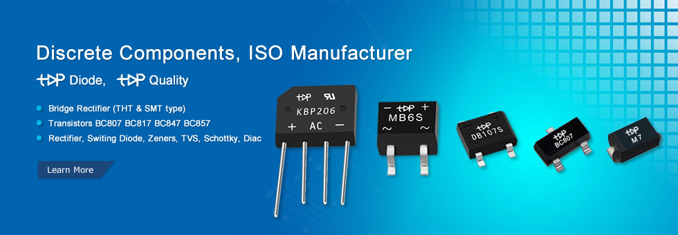
Typical Applications for Different Diode, Bridge, Transistor


Standard Recovery Rectifiers 50/60 Hz Rectification--> Polarity protection
Fast Recovery Rectifiers--> Rectification of medium frequencies
Ultrafast Recovery Rectifiers 50ns < trr < 100ns--> Rectification of high frequency
Superfast Recovery Rectifiers 15ns < trr < 75ns--> Rectification of high frequencies
Schottky Barrier Diode Output rectification--> Polarity protection
Zener Diodes--> Voltage stabilization
Transient Voltage Suppressor Diodes--> Overvoltage Protection
Current Limiting Diode--> Constant current source
Small Signal Diodes--> Signal processing
Single Phase Bridge Rectifiers--> Single phase input rectification
3 Phase Bridge Rectifiers--> Three phase input rectification
High Voltage Rectifiers--> Rectification of high voltages
Arrays--> Combination of diodes in SIL package
Bipolar Transistors--> Control and signal processing
Field Effect Transistors--> Control and signal processing
Diacs--> Trigger diodes

Solder & Assembly Instructions

At the maximum lead wire temperature of 260°C, the soldering time must not exceed 10s. This assumes that the solder joint is spaced not less than 5mm from the case. If the joint is spaced less than 5mm, the soldering time must be reduced to 3s.
 Dip or Wave Soldering
Leaded devices: At the maximum soldering temperature of 260°C, the soldering time must not exceed 10s (or two times 5s at dual wave soldering). The soldering joint should be spaced not less than 1.5mm from the case.
 SMD devices: The soldering time must not exceed 10s at 260°C when the device is submerged completely into the solder. At dual wave soldering, this corresponds to two times 5s.
 Reflow Soldering
For reflow soldering of SMD devices the maximum admissible solder temperature is 260°C, for package outlines up to SMC/DO-214AB and peak time not exceeding 5s. Time above 255°C must not exceed 30s. For bigger case outlines, the solder temperature must be reduced.

Email: info@topdiode.com  MSN: topdiode@gmail.com   Skype: topdiode  Website:www.topdiode.com

What is a Switching Diode?

What is a Switching Diode?
Switching diodes are a single p-n diode in a discrete package. A switching diode provides the same functionality as a switch. It has high resistance below the specified applied voltage similar to an open switch, whereas above that voltage it changes in a sudden way to the low resistance of a closed switch. Switching diodes are used in devices such as ring modulation.

Types of Switching Diodes:
There are many different kinds of switching diodes. At Topdiode, we supply many of the most common types categorized by power dissipation, maximum reverse recovery time, maximum reverse voltage, maximum average forward current, packaging type and maximum peak current. The most common values for power dissipation are 200 mW, 250 mW, 350 mW and 500 mW. Please refer to our products page.

Applications for Switching Diodes:
The switching diode is the most basic function of almost every electronic application. Switching diodes are also used in high-speed rectifying applications, such as in radiofrequency receivers. Applications also include high-speed switching, general-purpose switching and reverse polarity protection in the consumer, automotive, and telecommunication industry.

Switching Diodes from Topdiode:


Small Signal Switching Diode

Average Forward Current


Peak Repetitive Reverse Voltage 

0.3A

 100V

1N4148 DO-35

LL4148 LL-34

1N4148W SOD-123

1N4148WS SOD-323


MCL4148 MicroMELF


Silicon Epitaxial Planar Switching Diode

Average Forward Current


BAV99 SOT-23

200mA

BAV70 SOT-23


What is a Bridge Rectifier?

What is a Bridge Rectifier?  

A bridge rectifier is an arrangement of four or more diodes in a bridge circuit configuration which provides the same output polarity for either input polarity. It is used for converting an alternating current (AC) input into a direct current (DC) output. A bridge rectifier provides full-wave rectification from a two-wire AC input, therefore resulting in lower weight and cost when compared to a rectifier with a 3-wire input from a transformer with a center-tapped secondary winding.
Types of Bridge Rectifiers
There are many different kinds of bridge rectifiers at Topdiode, we supply many of the most common types categorized by maximum average rectified current, maximum reverse voltage, maximum peak current, forward voltage, packaging type and maximum reverse current.
 The most common sizes for maximum average rectified current are 1A, 1.5 A, 4 A, 25 A and 35 A. We also carry bridge rectifiers with maximum average rectified current as high as 1000 A. Forward voltage can range from 450 mV to 1.1 kV, with the most common bridge rectifier semiconductor chips having a forward voltage of 1.1 V or 1 V.
Bridge Rectifiers from Topdiode.
 Applications for Bridge Rectifiers:
The primary application of bridge rectifiers is to transform an AC supply into DC power. All electronic devices require direct current, so bridge rectifiers are used inside the power supplies of almost all electronic equipment. Bridge rectifiers are also used for detecting the amplitude of modulated radio signals. The signal may be amplified before it is detected. If it is not, then a very low voltage drop diode or a diode biased with a fixed voltage must be used. Rectifiers are also used to supply polarized voltage for welding applications. Control of the output current is required in such circuits, and this may be achieved by replacing some of the diodes in a bridge rectifier with thyristors, which are diodes whose voltage output can be regulated by switching on and off with phase fired controllers.
Bridge Rectifier from Topdiode
Topdiode has a full selection of bridge rectifier chips that can be used to design a full wave bridge rectifier circuit, half wave rectifier or any other type of circuits that may require a bridge rectifier. 

Through-hole Bridge Rectifier (THT type)


Peak Repetitive Reverse Voltage   

50V

100V

200V

400V

600V

800V

1000V

Average Forward Current

0.5A


MB2M

MB4M

MB6M

MB8M

MB10M

1.0A

DB101

DB102

DB103

DB104

DB105

DB106

DB107

1.5A

DB151

DB152

DB153

DB154

DB155

DB156

DB157


D2SB20

D2SB40

D2SB60

D2SB80


2.0A

GBL201

GBL202

GBL203

GBL204

GBL205

GBL206

GBL207

KBP201

KBP202

KBP203

KBP204

KBP205

KBP206

KBP207

3.0A

KBP301

KBP302

KBP303

KBP304

KBP305

KBP306

KBP307

4.0A

GBL401

GBL402

GBL403

GBL404

GBL405

GBL406

GBL407

KBJ4A

KBJ4B

KBJ4D

KBJ4G

KBJ4J

KBJ4K

KBJ4M

D3SB05

D3SB10

D3SB20

D3SB40

D3SB60

D3SB80


GBU4A

GBU4B

GBU4D

GBU4G

GBU4J

GBU4K

GBU4M

6.0A

KBJ6A

KBJ6B

KBJ6D

KBJ6G

KBJ6J

KBJ6K

KBJ6M

GBU6A

GBU6B

GBU6D

GBU6G

GBU6J

GBU6K

GBU6M

8.0A

GBU8A

GBU8B

GBU8D

GBU8G

GBU8J

GBU8K

GBU8M

KBJ8A

KBJ8B

KBJ8D

KBJ8G

KBJ8J

KBJ8K

KBJ8M

10A

GBU10A

GBU10B

GBU10D

GBU10G

GBU10J

GBU10K

GBU10M

KBJ10A

KBJ10B

KBJ10D

KBJ10G

KBJ10J

KBJ10K

KBJ10M


Surface Mount Bridge Rectifier (SMT type)


Peak Repetitive Reverse Voltage

50V

100V

200V

400V

600V

800V

1000V

Average Forward Current

0.5A


MB2S

MB4S

MB6S

MB8S

MB10S

0.8A


ABS2

ABS4

ABS6

ABS8

ABS10

1.0A

DB101S

DB102S

DB103S

DB104S

DB105S

DB106S

DB107S

1.5A

DB151S

DB152S

DB153S

DB154S

DB155S

DB156S

DB157S

Email: info@topdiode.com  MSN: topdiode@gmail.com   Skype: topdiode  Website:www.topdiode.com  

What is a Zener Diode?

What is a Zener Diode?

Zener diodes are a special kind of diode which permits current to flow in the forward direction. What makes them different from other diodes is that Zener diodes will also allow current to flow in the reverse direction when the voltage is above a certain value. This breakdown voltage is known as the Zener voltage. In a standard diode, the Zener voltage is high, and the diode is permanently damaged if a reverse current above that value is allowed to pass through it. Zener diodes are designed in a way where the Zener voltage is a much lower value. There is a controlled breakdown which does not damage the diode when a reverse current above the Zener voltage passes through a Zener diode.
Types of Zener Diodes
There are many different kinds of Zener diodes. Topdiode supply many of the most common types categorized by power dissipation, nominal working voltage, forward (drive) current, forward voltage, packaging type and maximum reverse current. The most common values for nominal working voltage are 5.1 V, 5.6 V, 6.2 V, 12 V and 15 V. Forward (drive) current can have a range from 200 uA to 200 A, with the most common forward (drive) current being 10 mA or 200 mA.
Applications for Zener Diodes
Zener diodes can be found in several applications. Some of these are: voltage stabilizers or regulators (in shunt mode), surge suppressors for device protection, peak clippers, switching operations, reference elements and in meter protection applications. The constant reverse voltage of a Zener diode renders it a very useful component in regulating the output voltage against variations in the load resistance or variations in the input voltage from an unregulated power supply. The current through the Zener diode will change in order to keep the voltage within the threshold limits of Zener action and the maximum power that it can dissipate.

Zener Diodes in Topdiode

Zener Diode 

Power dissipation

P/N

Voltage Range

500mW,1/2W

BZX55C2V7~47V DO-35

2.7V~47V

500mW,1/2W

BZV55C2V4~47V LL-34

2.4V~47V

1000mW, 1W

1N4729A~1N4756A DO-41

3.3V~100V

500mW

DL4728A ~DL4764A LL-41

3.3V~100V

0.35W

BZX84C3V0-47V

3V0~47V


What is a Fast Rectifier?

What is a Fast Rectifier?

Rectification is the most popular use for diodes. Fast rectifiers convert alternating current (AC) to direct current (DC). They only allow one-way flow of electrons. Rectifiers have many uses and are often found serving as components of high-voltage direct current power transmission systems and DC power supplies. Fast rectifier diodes feature very low reverse recovery time, very low switching losses and low noise turn-off switching.
Types of Fast Rectifiers
There are several different kinds of fast rectifiers. At Topdiode we offer many of the most common types categorized by maximum average rectified current, maximum reverse recovery time, maximum reverse current, maximum reverse voltage, packaging type and forward voltage. The most common sizes for forward voltage are 1.1 V, 1.2 V and 1.3 V.
 Applications for Fast Rectifiers:
Fast rectifier diodes are found in strobe applications that require high surge resistance as well as in the industrial, commercial and automotive sectors. High voltage resistance fast rectifier diodes, which are ideal for use in switching power supplies of all types, feature fast switching speeds along with improved efficiency and reduced loss. Fast rectifiers are also used in PDPs (sustain circuits) and PFC circuits. Also, detectors of radio signals serve as rectifiers.

Fast Recovery Rectifiers in Topdiode

Fast Recovery Diode


Peak Repetitive Reverse Voltage 

50V

100V

200V

400V

600V

800V

1000V


1.0A

1N4933

1N4934

1N4935

1N4936

1N4937


BA157

BA158

BA159D

BA159

FR101

FR102

FR103

FR104

FR105

FR106

FR107

1.5A

FR151

FR152

FR153

FR154

FR155

FR156

FR157

2.0A

FR201

FR202

FR203

FR204

FR205

FR206

FR207

2.5A

FR251

FR252

FR253

FR254

FR255

FR256

FR257

3.0A

FR301

FR302

FR303

FR304

FR305

FR306

FR307

5.0A

FR501

FR502

FR503

FR504

FR505

FR506

FR507

6.0A

FR601

FR602

FR603

FR604

FR605

FR606

FR607

Email: info@topdiode.com  MSN: topdiode@gmail.com   Skype: topdiode  Website:www.topdiode.com  

What is a Schottky Diode?

What is a Schottky Diode?

A Schottky diode, also known as a hot carrier diode, is a semiconductor diode which has a low forward voltage drop and a very fast switching action. There is a small voltage drop across the diode terminals when current flows through a diode. A normal diode will have a voltage drop between 0.6 to 1.7 volts, while a Schottky diode voltage drop is usually between 0.15 and 0.45 volts. This lower voltage drop provides better system efficiency and higher switching speed. In a Schottky diode, a semiconductor–metal junction is formed between a semiconductor and a metal, thus creating a Schottky barrier. The N-type semiconductor acts as the cathode and the metal side acts as the anode of the diode. This Schottky barrier results in both a low forward voltage drop and very fast switching.
Applications for Schottky Diodes:
Schottky diodes are useful in voltage clamping applications and prevention of transistor saturation due to the higher current density in the Schottky diode. Also, because of the low forward voltage drop in a Schottky diode, less energy is wasted as heat, therefore making them an efficient choice for applications that are sensitive to efficiency. Because of this, they are used in stand-alone photovoltaic systems in order to prevent batteries from discharging through the solar panels at night as well as in grid-connected systems containing multiple strings connected in parallel. Schottky diodes are also used as rectifiers in switched-mode power supplies. 

 Email: info@topdiode.com  MSN: topdiode@gmail.com   Skype: topdiode  Website:www.topdiode.com  

聚合内容