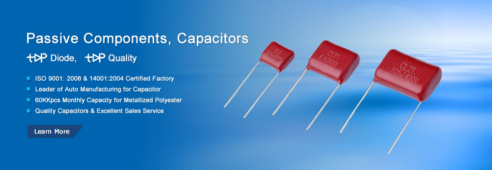
• 1
  • 2
  • 3
  • 4

Plastic film capacitor

Plastic film capacitor
In film capacitors, plastic film is used to construct the dielectric and aluminum or zinc is used to construct the electrodes of the capacitor. Film capacitors are also known as plastic film capacitors or film dielectric capacitors. Plastic film capacitors are mainly used in circuits where low loss and high insulation resistance is required.


Plastic film capacitor definition
Plastic film capacitor is a capacitor that uses plastic film as the dielectric and aluminum or zinc as the electrodes to store electric charge.
What is dielectric?
Dielectric is the insulating material placed between the electrodes of a capacitor. Dielectric materials are chosen based on their ability to allow electrostatic attraction and repulsion. Good dielectric materials are poor conductors of electricity. However, they allow the electrostatic field.
In plastic film capacitors, polyester, polypropylene, polyethylene terephthalate, and polyphenylene sulfide are commonly used as dielectrics.
Types of plastic film capacitors
Film capacitors are classified into two types:
Film-foil capacitors
Metallized film capacitors
Film-foil capacitors
The film-foil capacitor is made of two plastic films or sheets; each is layered with thin aluminum metal foil or sheet. The plastic sheets and aluminum sheets are then rolled in the form of a cylinder and wire leads are attached to the both ends of aluminum sheets. Polyester, polypropylene, polyethylene terephthalate, and polyphenylene sulfide are commonly used as dielectric in film capacitors. In plastic film capacitors, aluminum sheets acts as electrodes and plastic sheets acts as dielectric.
The film-foil capacitor is made of two plastic films; each is layered with thin aluminum metal foil.
Metallized film capacitors
In metallized film capacitors, the aluminum sheet or foil is replaced by a layer of metal vacuum deposited on the film layer. The most commonly used metal layer is aluminum or zinc that is extremely thin.
In metallized film capacitors, the aluminum foil is replaced by a layer of metal vacuum deposited on the film layer. The most commonly used metal layer is aluminum or zinc that is extremely thin.The plastic film layers made of synthetic material act as dielectric and the aluminum layers act as electrodes. The major advantage of film dielectric capacitors over natural dielectric capacitors is that the plastic film is synthetic or artificial. Therefore, we can able to increase thickness and heat resistance of the dielectric. In other words, we can change the thickness and heat resistance of the plastic film capacitor.
Applications of film capacitors
The various applications of film capacitors include:
A/D converters
Filters
Motor run
Peak voltage detectors
Advantages of film capacitors
High stability
Low cost
Low losses even at high frequencies


Semiconductor chips shortage will extend to 2022


Semiconductor chips shortage will extend to 2022

By Jack Li 2021.12.23


According to VP of SMIC, semiconductor chips shortage will extend to 2022. Topdiode Group, a discrete semiconductors manufacturer and discrete semiconductors supplier, offer a series of tvs diodes, transistors, mosfet. Currently, some items lead time is improved to 4 weeks. And there are some transistors, mosfet whose lead time are more than 10 weeks. If you need Topdiodes semiconductors: TVS diodes SMAJ SERIES, SMBJ SERIES, SMCJ SERIES, SMDJ SERIES, pls contact: wa.me/8613612654974

A few days ago, the annual China Integrated Circuit Design Industry 2021 Conference (ICCAD 2021) was grandly opened in Wuxi, Jiangsu.


At the summit forum held at the same time, Mr. Peng Jin, senior vice president of Semiconductor Manufacturing International Co., Ltd. SMIC, the biggest Semiconductors factory in China, delivered a speech titled "Docking the Whole Machine Enterprise, Coordinating Industry Supply". In this speech, he mentioned that in his It seems that throughout 2022, the capacity of wafer and chips is still tight, and there is an overbooking situation in the industry. However, SMIC will continue to invest firmly and continuously to help the global chip industry chain overcome difficulties and join hands to move towards a new future for the chip industry.


Peng Jin said that the continuous shortage of chip production capacity is caused by the combined influence of multiple factors such as the epidemic, geopolitics and demand.

According to him, the emergence of the above-mentioned factors has prompted Chinese complete machine companies, including mobile phones, automobiles, home appliances and screen manufacturers, to increase their stocks in the past year or so, making chips a reserve material; at the same time, they are still working hard. Seek localized chip design and manufacturing. Especially in terms of manufacturing, even if there are some chips that China cannot design at present, they also hope that overseas companies can switch to Chinese manufacturing in a planned way, which brings huge demand to the design and manufacturing of domestic integrated circuits.

Peng Jin took the development of domestic screen factories as an example to explain why chips have become the bottleneck of industrial development. According to him, if only the production capacity of domestic AMOLED is counted, it can fully meet the needs of domestic mobile phone manufacturers, but because of the capacity limitation of the driver chip, it affects the power of the terminal.

In addition to the limited capacity of existing chips, new demand brought about by new applications has become another key factor affecting supply.

Peng Jin mentioned in his speech that in 2021, the domestic sales of new energy vehicles will reach 3.2 million, and the production and sales far exceed expectations at the beginning of the year. At the same time, new energy vehicles themselves have more demand for chips, and the resulting production capacity tension is obvious. "Each new energy vehicle needs an 8-inch silicon chip. Among them, discrete devices IGBT account for 0.4, DMOS account for 0.1, and the other 0.5 belong to integrated circuits such as MCU, power management and high-performance computing." Peng Jin said for example. "According to relevant forecasts, the national sales of new energy vehicles will reach 6 million next year. If calculated in this way, 2.8 million new energy vehicles will be added next year, which means that at least 1.4 million 8-inch silicon wafers will be needed to meet this requirement. Demand." Peng Jin continued.

In addition, in Peng Jin's view, carbon neutrality promotes analog semiconductor opportunities in the industrial equipment and automotive markets, and AIoT also brings more demand for wireless chips and microcontrollers.

"At present, the focus of the industry will shift from products that used to be digital IC-based products such as mobile phones, computers, and televisions, to areas that are dominated by analog IC demand. These analog chips, including power management and CIS, will bring huge benefits in the future. Opportunity." Peng Jin emphasized. From the data he provided, we can see that, driven by chips such as automobiles, power management, and communications, the growth rate of analog ICs will be about 10% from now to 2025, and the demand for analog ICs in China will reach 28.5 billion next year. US dollars. Although many domestic companies in this field have already gone public, there are still many companies that are rapidly establishing and growing. "Peng Jin concluded that this can also explain the important reasons for the shortage of certain products during this period.

"The repeated construction of the global semiconductor market that does not follow the market demand has pushed up the equipment delivery cycle, which has slowed the expansion of the fab, and further affected the supply of chips. From his introduction, we learned that the delivery of equipment The period has been extended from only half a year before to one year or even one and a half years now. According to a recent report by the well-known analyst firm Omdia, Chinas fabless fabs are actively entering the AMOLED-driven market, but because there are only a limited number of crystals. OEMs can provide production capacity for high-voltage (HV) 40nm and 28nm AMOLED driver chips. However, first-tier brands or fabless fabs will occupy most of the foundry capacity in 2022. Therefore, only a small amount is left. Production capacity is left to Chinese panel makers. "In the third quarter of last year, smartphone-related businesses accounted for 46% of the company's total revenue, but this year this figure is only 32%. But the Internet of Things, computer and automotive businesses, which accounted for 16% last year, doubled to 32% this year. "Peng Jin said for example.

Finally, Peng Jin also introduced SMIC's future technology layout. He pointed out that SMIC will continue to consolidate its original special storage and CIS advantages, and will also invest in display, MCU, analog, automotive and radio frequency fields. "In the key development areas mentioned above, SMIC will continue to invest in research and development and will also expand its production capacity."


How to correctly determine the positive and negative poles of chip tantalum capacitors?

  How to correctly determine the positive and negative poles of chip tantalum capacitors?

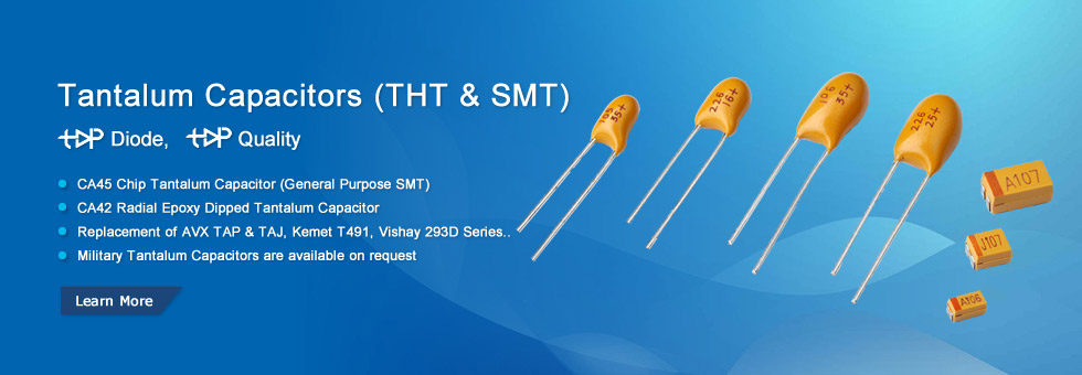
  One end of the chip tantalum capacitor is marked with a horizontal line, which is the positive electrode of the chip tantalum capacitor, and the other end is the negative electrode. The long end of the lead tantalum capacitor is the positive electrode, and the short end is the negative electrode.

  SMD tantalum capacitors are polar capacitors. The positive and negative poles cannot be reversed. In case of reverse connection, the tantalum capacitor will not work or fail.

  The positive and negative poles of SMD tantalum capacitors are distinguished and measured. The black block with the mark on the tantalum capacitor is the negative pole. There are two semicircles on the capacitor position on the PCB, and the pin corresponding to the colored semicircle is the negative pole. The length of the pins is also used to distinguish the positive and negative poles as positive and short pins as negative.

  When we don’t know the positive and negative poles of SMD tantalum capacitors, we can use a multimeter to measure them. The medium between the two poles of the capacitor is not an absolute insulator, and its resistance is not infinite, but a finite value, generally above 1000 megohms. The resistance between the two poles of the capacitor is called insulation resistance or leakage resistance, and only electrolytic capacitors When the positive pole of the electrolytic capacitor is connected to the positive power supply (the black test lead when the electricity is blocked), and the negative terminal is connected to the negative power supply (the red test lead when the electricity is blocked), the leakage current of the electrolytic capacitor is small (the leakage resistance is large).


Chip MLCC Capacitors Compound Annual Growth Rate

  Chip MLCC Capacitors Compound Annual Growth Rate

  What is CAGR, CAGR means Compound annual growth rate, annual growth rate of an investment over a specified period of time longer than one year.  Chip MLCC CAGR is around 8%! Until end of 2021, some manufacturers still offer chip mlcc with 20 weeks. MLCC have a increasing demand.

  Why engineers prefer to use chip mlcc?

  a.  chip mlcc have small size

  b.  chip mlcc is cost effective

  c.  chip mlcc technology have big improvement, especially in large capacitance and high voltage.

  d.  tantalum capacitors are unstable in supply, and prices very expensive.

  With the delay in 2021, new MLCC spot shortages have forced some industries to become agile and adapt to supply chain fluctuations.

  Through 2021, the shortage of automotive chips remains the same. Although companies such as Intel and TSMC are investing in increasing fab capacity, many in the industry and the financial industry predict that the shortage will continue into 2023. The price tag is also shocking. It is estimated that the loss of income will now exceed 100 billion US dollars. Take the automobile industry as an example.

  The shortage of electronic components is nothing new in 2020 and 2021. In 2020, this is due to everyone staying at home for reasons such as vacations, panic buying, excessive demand for home-working electronics, and/or forced lockouts. By 2021, pent-up consumer demand, capital expenditures, and investment in reopening games appear to be creating shortages in everything from wood to plastic.

  The repeated shortage in 2017 is rooted in the shortage of multilayer ceramic capacitors (MLCC). The shortage of these components began to reach a worrying level in 2018 and then eased in 2019. In 2020, COVID-19 has caused obvious problems in global manufacturing capacity, renewing concerns about the shortage of MLCC. By mid-2021, due to supply chain issues in industrial, medical, and military systems, concerns about the shortage of MLCC continue, especially now that more than one manufacturer has sounded the alarm. There are now some questions as to whether the overall shortage will extend beyond these specific industries and affect the broader electronics market. If you are planning a design that requires MLCC, you may need to plan alternatives in case the components you need are out of stock and have a long lead time.

  Who may be affected by the MLCC shortage?

  The current wave of MLCC shortages is affecting many industries other than automobiles. Of course, in addition to a large number of other electronic products, automobiles also need capacitors, but the industries that have recently made headlines are defense electronics, medical equipment, and industrial automation.

  So is this a supply-driven or demand-driven shortage? Interestingly, the inventory problems in these industries are a bit of both. Some products that drive MLCC inventory consumption include:

  Low-power radar, radio and wireless network products operating at GHz frequency

  Devices that support 5G, such as mobile phones, IoT products, base station equipment and other telecommunication equipment

  Consumer electronics products (laptops, smart phones, etc.) now require more MLCC than a few years ago

  MLCC in these products is used very much, and small-case capacitors (<0603) are used. In particular, these components are low-Q, low-voltage capacitors used to achieve broadband decoupling and filtering to high frequencies in products with radio frequency capabilities. When you consider that the average smartphone or tablet computer contains more small-case capacitors than ever before, the demand and market size in this area have motivated MLCC manufacturers to shift their capacitors to meet the needs in these areas.

  Therefore, industrial, medical, and military products that require high-voltage, high-Q MLCCs are facing pressure to reduce inventory of large-size MLCCs. Affected products include power supplies/regulators, MRI coils, amplifiers, lasers, and many other specialized products that require larger enclosures.

  Adapt to changing supply

  In order to adapt to the growth in demand for consumer electronics products (mainly smartphones, tablets and other products) last year, most of the manufacturing capabilities of MLCCs have shifted from high-Q/high-voltage capacitors to smaller, lower-Q capacitors. These are physically Smaller components tend to have lower voltage ratings and higher self-resonance; the lower voltage ratings of smaller housing sizes make them less useful in the affected industries. In addition, strict gap restrictions in smaller consumer devices limit the use of larger housing sizes because they may not be suitable for smaller housings for consumer devices.

  Considering the needs of various housing sizes and the shift to consumer electronics, I don’t think we should be surprised by these developments. Compared with the situation in 2018, the total inventory data of distributors shows that it is difficult to call this a full-scale MLCC shortage because, as mentioned above, it does not affect all industries or manufacturers. However, the inventory throughout the supply chain has been steadily decreasing. This emphasizes the need for design teams to plan ahead and consider replacing their products.

  At present, American EMS suppliers are transferring their onshore production capacity or adding new production capacity online to solve the shortage of the entire supply chain. Time will tell how this particular part of the capacitor market will develop and whether demand will continue to consume capacitor inventories in the long term. At the same time, PCB designers and engineers need to consider how to adjust their designs to withstand the MLCC shortage and continue to bring products to the market.

  Supply chain visibility helps companies stay agile

  The growth of consumer electronics products and the recurring business cycles of the electronics industry will continue to put pressure on the MLCC supply chain. Even after the input capacity helps alleviate the current shortage, I expect that we will reappear in the next business cycle. When the inventory of distributors and manufacturers fluctuates, companies large and small that use MLCC for design need to remain agile. Make sure to use the best electronic supply chain tools and search engines to browse the distributor’s inventory and find replacement parts. When you understand the supply chain when you plan to enter the manufacturing phase, you can ensure that your products can be mass-produced on time.

  Even if chip mlcc shortage happen again in 2022, Topdiode Group UF Capacitors, as a chip MLCC capacitors supplier, we have enough capacity to ship within 2 weeks.


What is an LED driver?

  Topdiode Group & UF Capacitors provide components solution for below: Led control circuit; SMPS for LED TV, SMPS circuit; ESL.

  Basic knowledge of drive


  What is an LED driver?


  The LED driver changes the power supply to a specific voltage and current to drive the LED voltage converter. Generally speaking, the input of the LED driver includes high-voltage power frequency AC (ie, mains), low-voltage DC, high-voltage DC, and low-voltage and high-frequency AC (such as the output of electronic equipment). transformer). The output of the LED driving power supply is mostly a constant current source, and the voltage can be changed as the forward voltage drop of the LED changes. The core components of LED power supply include switching controller, inductor, switching element (MOSFET), feedback resistor, input filter, output filter, etc. According to the requirements of different occasions, there must be input overvoltage protection circuit, input undervoltage protection circuit, LED open circuit protection,

  Electronic Shelf Label (ESL) Circuit, PCB Assembling

  Low loss rectifier circuit 

  Multi-channel LED control 

  SMPS for LED TV

  LCD TV SMPS

  Electronic Shelf Label circuit use 100uF 6.3V A case tantalum capacitors, in the past, only AVX Capacitors can provide 100uF in A case. We Topdiode UF Capacitors, #Chinacapacitorsfactory#chinacapacitorssupplier have mature technology, and we can supply 100uF in A case.

  6.3V 100UF 107J TAJA107K006RNJ A case ±10% 1206 SMD Tantalum Capacitors

  SMD tantalum capacitor 100UF 3216 AVX TAJA107K006RNJ 6.3V type A

  TAJA685K016RNJ 16V 6.8UF 685C A case ±10% 1206 SMD Tantalum Capacitors

  6V 47UF A case 476C ±10% 1206 SMD Tantalum Capacitors 3.2mm×1.6mm

  16V 10UF B case 106C TAJB106K016RNJ 1210 ±10% SMD Tantalum Capacitors

  16V 4.7UF 475C TAJA475K016RNJ A case ±10% 1206 SMD Tantalum Capacitors


How to correctly determine the positive and negative poles of chip tantalum capacitors?

How to correctly determine the positive and negative poles of chip tantalum capacitors?

           One end of the chip tantalum capacitor is marked with a horizontal line, which is the positive electrode of the chip tantalum capacitor, and the other end is the negative electrode. The long end of the lead tantalum capacitor is the positive electrode, and the short end is the negative electrode.


   SMD tantalum capacitors are polar capacitors. The positive and negative poles cannot be reversed. In case of reverse connection, the tantalum capacitor will not work or fail.
   The positive and negative poles of SMD tantalum capacitors are distinguished and measured. The black block with the mark on the tantalum capacitor is the negative pole. There are two semicircles on the capacitor position on the PCB, and the pin corresponding to the colored semicircle is the negative pole. The length of the pins is also used to distinguish the positive and negative poles as positive and short pins as negative.
   When we don’t know the positive and negative poles of SMD tantalum capacitors, we can use a multimeter to measure them. The medium between the two poles of the capacitor is not an absolute insulator, and its resistance is not infinite, but a finite value, generally above 1000 megohms. The resistance between the two poles of the capacitor is called insulation resistance or leakage resistance, and only electrolytic capacitors When the positive pole of the electrolytic capacitor is connected to the positive power supply (the black test lead when the electricity is blocked), and the negative terminal is connected to the negative power supply (the red test lead when the electricity is blocked), the leakage current of the electrolytic capacitor is small (the leakage resistance is large).


What are TVS Diodes?

  What are TVS Diodes?

  By Kelvin Tan

  TVS Diodes are electronic components designed to protect sensitive electronics from high-voltage transients. They can respond to overvoltage events faster than most other types of circuit protection devices, and are offered in a variety of surface mount and through-hole circuit board mounting formats.

  They function by limiting voltage to a certain level (referred to as a "clamping" device) with p-n junctions that have a larger cross-sectional area than those of a normal diode, allowing them to conduct large currents to ground without sustaining damage.

  TVS Diodes are generally used to protect against electrical overstress such as those induced by lightning strikes, inductive load switching, and electro-static discharge (ESD) associated with transmission on data lines and electronic circuits.

  topdiode TVS Diodes can fit a wide range of circuit protection applications but were primarily designed to protect I/O interfaces in telecommunication and industrial equipment, computers and consumer electronics.

  topdiode TVS Diode characteristics include:

  Low incremental surge resistance

  Unidirectional and Bidirectional polarities available

  Reverse standoff voltages range from 5 to 512V

  RoHS compliant–Matte Tin Pb-free plated

  Surface-mount power ratings from 400W to 5,000W

  Axial lead power ratings from 400W to 30,000W (30kW)

  High current protection available for 6kA and 10kA

  TVS Diode Glossary

  Clamping Device

  TVS is a clamping device that limits voltage spikes by low impedance avalanche breakdown of a rugged silicon PN junction. It is used to protect sensitive components from electrical overstress generated by induced lightning, inductive load switching and electrostatic discharge.

  Operating Temperature Range

  The minimum and maximum ambient operating temperature of the circuit in which a device will be applied. Operating temperature does not allow for the effects of adjacent components, this is a parameter the designer must take into consideration.

  Capacitance

  The property of a circuit element that permits it to store an electrical charge. In circuit protection, the off-state capacitance is typically measured at 1 MHz with a 2V bias applied.

  Reverse Standoff Voltage (VR)

  In the case of a uni-directional TVS diode, this is the maximum peak voltage that may be applied in the 'blocking direction' with no significant current flow. In the case of a bi-directional transient, it applies in either direction. It is the same definition as Maximum Off-state Voltage and Maximum Working Voltage.

  Breakdown Voltage (VBR)

  Breakdown voltage measured at a specified DC test current, typically 1mA. Usually a minimum and maximum is specified.

  Peak Pulse Current (IPP)

  Maximum pulse current which can be applied repetitively. Usually a 10x1000μs double exponential waveform, but can also be 8x20μs, if stated.

  Maximum Clamping Voltage (VC or VCI)

  Maximum voltage which can be measured across the protector when subjected to the Maximum Peak Pulse Current.

  Peak Pulse Power (PPP)

  Expressed in Watts or Kilowatts, for a 1ms exponential transient  it is IPP multiplied by VCL.


  P4KE6.8-P4KE440CA Axial Leaded 400W TVS Diode P4KE series

  P6KE6.8-P6KE440CA Axial Leaded 600W TVS Diodes P6KE series

  SMAJ5.0--SMAJ440CA Surface Mount TVS -Topdiode

  SMBJ5.0--SMBJ440CASurface Mount TVS -Topdiode

  SMCJ5.0-SMCJ440CA 1500W Suface Mount TVS Diode Topdiode

  TVS DIODE SD03, SD05, SD12-Topdiode

  5.0SMDJ12A-CA-5.0SMDJ170A-CA-Topdiode

  SMDJ5.0--SMDJ170CA-Surface Mount TVS -Topdiode

  ESD3Z_SERIES SOD-323-Topdiode

  SMA6J5.0--SMA6J200CA-Topdiode

  TVS Diodes P6SMB6.8-440ACA Topdiode

  TVS Diodes-P4SMA6.8-440ACA

  1.5KE6.8A-THRU-1.5KE600A-Topdiode


RoHS VS PB FREE

  RoHS VS PB FREE
  By Kelvin Tan
  What is RoHS? What is RoHS 2.0? What is RoHS 3.0?


  Directive 2011/65/EU was published in 2011 by the EU, which is known as RoHS-Recast or RoHS 2. RoHS 2 includes a CE-marking directive, with RoHS compliance now being required for CE marking of products. RoHS 2 also added Categories 8 and 9, and has additional compliance recordkeeping requirements.
  Directive 2015/863 is known as RoHS 3. RoHS 3 adds four additional restricted substances (phthalates) to the list of six.
  As now China's test lab does not have RoHS 3.0 test standard. So Topdiode and UF Capacitors only declare our products are RoHS 2.0 Compliant. We will update our certification according to latest regulations.
  RoHS Compliant for 2022
  Any business that sells applicable electrical or electronic products, equipment, sub-assemblies, cables, components, or spare parts directly to RoHS-directed countries, or sells to resellers, distributors or integrators that in turn sell products to these countries, is impacted if they utilize any of the restricted 10 substances.
  With the rapid spread of digitization, the world's production of electrical and electronic devices is exploding. Besides mobile devices, think about the coming wave of IoT, smart home assistants, robots, drones, 3D printers, and home medical devices to all corners of the planet...they are all regulated under RoHS.
  EU RoHS specifies maximum levels for the following 10 restricted substances. The first six applied to the original RoHS while the last four were added under RoHS 3, which took effect July 22, 2019.
  Cadmium (Cd): < 100 ppm
  Lead (Pb): < 1000 ppm
  Mercury (Hg): < 1000 ppm
  Hexavalent Chromium: (Cr VI) < 1000 ppm
  Polybrominated Biphenyls (PBB): < 1000 ppm
  Polybrominated Diphenyl Ethers (PBDE): < 1000 ppm
  Bis(2-Ethylhexyl) phthalate (DEHP): < 1000 ppm
  Benzyl butyl phthalate (BBP): < 1000 ppm
  Dibutyl phthalate (DBP): < 1000 ppm
  Diisobutyl phthalate (DIBP): < 1000 ppm
  About Lead-Free and RoHS
  In practice, RoHS-compliant is often equated with “lead-free”. However, this is a widespread mistake. The RoHS directive 2002/95/EC aims to minimize the use of hazardous substances (including, among others, lead), but it does not completely exclude a small percentage. One of the great obstacles in implementing the directive was the switchover to lead-free solder, because the limit values (0.1 per cent by weight of the inseparable components) do not admit a lead solder. This is probably the most important reason for the mix-up/equating that comes up again and again.
  Due to environmental concerns, the need for lead-free solutions in electronic components and systems is receiving increasing attention within the semiconductor and electronics industries.
  In a word, Lead Free and Pb Free is the same thing. Due to worldwide environmental restricted chemical and material (RCM) concerns, it was determined lead (Pb) as one of the major substances of concerns. Lead-free devices in electronic components and systems continues to receive significant attention within the semiconductor and electronics industry as a whole.
  Lead Free and Pb Free mean "No PB Process". PB Free and Lead-Free electronics components are definitely RoHS Compliant. But RoHS Compliant did not mean Pb Free of Lead Free.
  RoHS Compliant means lead <1000 PPM, and also accept exemption sometimes.
  Ps: Green products mean stricter: Lead (Pb): < 90 ppm
  Topdiode & UF Capacitors’ all components are RoHS Compliant. But not all our electronic components are PB Free or Lead-Free. If you require Lead-Free, pls check case by case.


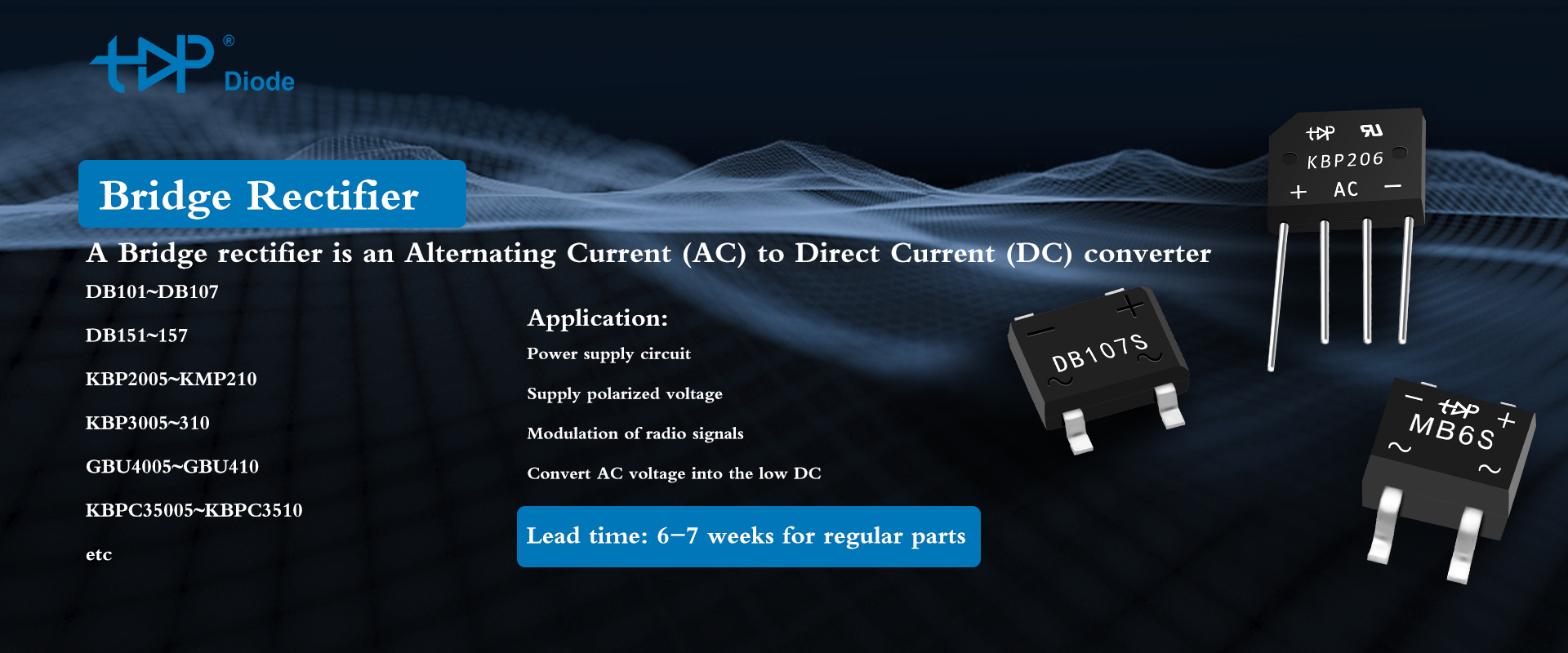
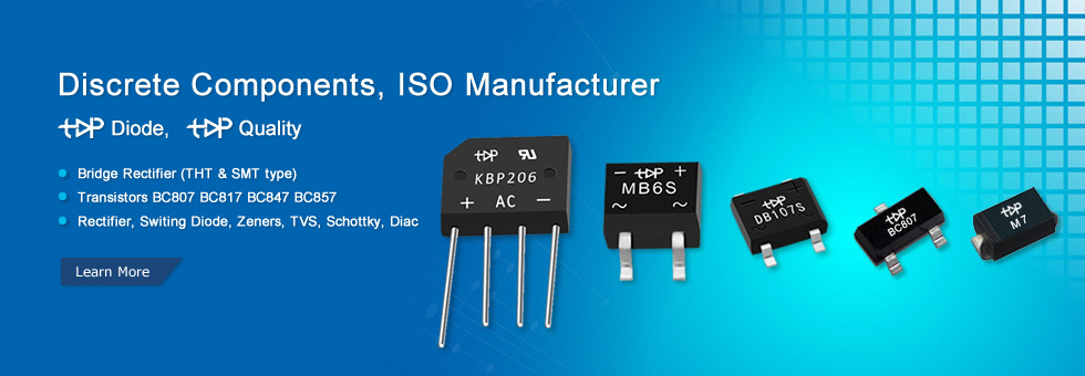
Topdiode DB107S

Topdiode DB107S, Bridge Rectifier, 1A 1000V, 4-Pin DBS

  Manufacturer Topdiode part number: DB107S
  Gross weight: 0.378 g
  Bridge rectifier: single-phase; 1000V; If: 1A; SMT Bridge Rectifier,
  DB101S THRU DB107S  Single Phase, Glass Passivated Silicon Bridge Rectifier
  RoHS Reach compliant
  Topdiode L/T: 3-4 wks
  #Rectifler#Single-phasebridgetypefullycontrolledrectifiercircuit#Bridgerectifier#Theroleofthe rectifier#Electronic#rectifier##diode#shortage#chinasupply#maker#electroniccomponents#discrete#semiconductors#transistors#mosfet#diodes#chinabridgefactory#

聚合内容